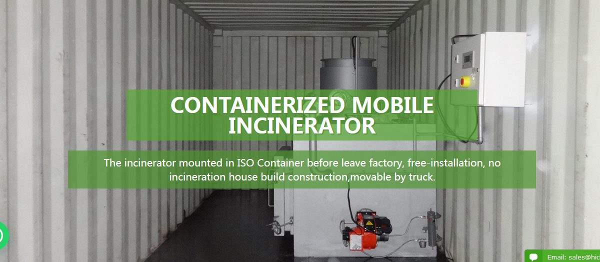
Containerized Mobile Incinerator(CA Model)
HICLOVER now offer a full range of containerized incineration systems, placing us at the forefrontof the latest transportation and industrial trends. Containerization enables immediate wastemanagement as the units are pre-assembled and pre-installed.
Containerization is the most feasible and viable option in contrast to the construction of on-sitefacilities and housing structures, eliminating the man power and costs involved. The systemhas the added benefit of total mobility (both local and international), and is ideal for militaryand civil camps and remote locations where infrastructure is scarce.
※Main Feature:
— Double Combustion Chamber
— Double Italy Burner
–Burning Rate: 10-100kgs per hour
–Combustion Chamber: 0.1M3-1.2M3
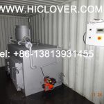
— Mobile Incinerator, Standard shipping containers, Easy to move/transport system
— Free Installation, Pre-installed incinerator, Ideal for camps
— Ultraviolet lamp sterilization insideNanjing Clover Medical Technology Co.,Ltd.Tel: +86-25-8461 0201
Mobile: +86-13813931455(whatsapp/wechat)
Website: www.hiclover.com
Email: [email protected]
Email: [email protected]
Items/Model TS10(PLC) TS20(PLC) TS30(PLC) TS50(PLC) TS100(PLC) Burn Rate (Average) 10 kg/hour 20 kg/hour 30 kg/hour 50 kg/hour 100 kg/hour Feed Capacity(Average) 20kg 40kg 60kg 100kg 200 kg Control Mode PLC PLC PLC PLC PLC Combustion Chamber 100L 210L 330L 560L 1200L Internal Dimensions 50x50x40cm 65x65x50cm 75x75x60cm 100x80x70cm 120x100x100cm Secondary Chamber 50L 110L 180L 280L 600L Smoke Filter Chamber Yes Yes Yes Yes Yes Feed Mode Manual Manual Manual Manual Manual Voltage 220V 220V 220V 220V 220V Power 0.5Kw 0.5Kw 0.5Kw 0.7Kw 0.7Kw Oil Consumption (kg/hour) 5.4–12.6 7.8–16.3 10.2–20 12.1–24 14–28 Gas Consumption (m3/hour) 6.2–11.4 8–15.7 9.8–20 9.9–26.1 10–32.2 Temperature Monitor Yes Yes Yes Yes Yes Temperature Protection Yes Yes Yes Yes Yes Oil Tank 100L 100L 100L 100L 200L Feed Door 30x30cm 45x40cm 55x50cm 70x55cm 80x60cm Chimney 3Meter 3Meter 5Meter 5Meter 10Meter Chimney Type Stainless Steel Stainless Steel Stainless Steel Stainless Steel Stainless Steel 1st. Chamber Temperature 800℃–1000℃ 800℃–1000℃ 800℃–1000℃ 800℃–1000℃ 800℃–1000℃ 2nd. Chamber Temperature 1000℃-1200℃ 1000℃-1200℃ 1000℃-1200℃ 1000℃-1200℃ 1000℃-1200℃ Residency Time 2.0 Sec. 2.0 Sec. 2.0 Sec. 2.0 Sec. 2.0 Sec. Gross Weight 1500kg 2200kg 3000kg 4500kg 6000kg External Dimensions 140x90x120cm 160x110x130cm 175x120x140cm 230x130x155cm 260x150x180cm Water treatment system
Water softener or R/O system shall be delivered with a capacity adapted to the need of the above steamtreatment system. The bidder shall indicate the capacity of the unit offered. To ensure good steam quality,the contaminants in the feed water supplied to a steam generator in which no additional water treatmentis incorporated should not exceed the following parameters. If these parameters cannot be complied with,an additional feed water treatment system shall be supplied (Water softener or R/O System)
“The water treatment plant to be supplied shall be able to supply the steam generator of the treatmentplant with a sufficient quantity of water with the following quality:
Determinant: Feed water:
1) Evaporation residue < 10 mg/l
2) Silicium oxide, SiO2 < 1 mg/l
3) Iron < 0.2 mg/l
4) Lead < 0.05 mg/l
6) Chloride (Cl’) < 2 mg/l
7) Phosphate (P2O5) < 0.5 mg/l
8) Conductivity (at 20 °C) < 15 μs/cm
9) pH value (degree of acidity) 5 to 7.5
10) Hardness (Σ Ions of alkaline) < 0.02 mmol/l
“
Compressed air generator
A compressed air generator has to be supplied for the pneumatic system of the treatment plantand for maintenance purposes.
The compressed air supplied should have a pressure of 500 kPa to 700 kPa (5 bar to 7 bar), shall befree of liquid water, shall be filtered to 25 μm and shall be free from oil droplets greater than 2 μm.
Uninterruptible Power System (UPS)
UPS system will be provided to brige over times of power cut for the PLC of the treatment plant.The UPS shall automatically maintain AC power within specified tolerances to the critical load,without interruption, during failure or deterioration of the normal power source. The manufacturershall design and furnish all materials and equipment to be fully compatible with electrical, environmental,and space conditions at the site. It shall include all equipment to properly interface the AC power sourceto the intended load and be designed for unattended operation. AC Output and Input shall be designedto support the PLC and all electrical systems of the treatment plant and the steam generator(without heating elements) for at least 10 minutes.
The UPS and all associated equipment shall be manufactured in accordance with the followingapplicable standards: CSA 22.2, No. 107.1, IEEE 587, Category B (ANSI C62.41), National ElectricalCode (NFPA 70), NEMA PE-1, UL Standard 1778.
The Quality System for the engineering and manufacturing facility shall be certified to conform toQuality System Standard ISO 9001 for the design and manufacture of power protection systemsfor computers and other sensitive electronics.
“The UPS shall operate as an on-line reverse transfer system in the following modes:
A. Normal: The critical AC load is continuously powered by the UPS inverter. The rectifier/ chargerderives power from the utility AC source and supplies DC power to the inverter, while simultaneously float charging the battery.
B. Emergency: Upon failure of utility AC power, the critical AC load is powered by the inverter which,without any switching, obtains its power from the battery plant. There shall be no interruption inpower to the critical load upon failure or restoration of the utility AC source.
C. Recharge: Upon restoration of the utility AC source, the rectifier/charger powers the inverterand simultaneously recharges the battery. This shall be an automatic function and shall cause no interruption to the critical AC load.
D. Bypass: If the UPS must be taken out of service for maintenance or repair, the static transferswitch shall transfer the load to the bypass source. The transfer process shall cause no interruption in power to the critical AC load.
E. Off-Battery: If the battery only is taken out of service for maintenance, it is disconnected from the rectifier/chargerand inverter by means of (an) external disconnect breaker(s). The UPS shall continue to function and meet allof the specified steady-state performance criteria, except for the power outage back-up time capability.
“
The maximum working voltage, current, and di/dt of all solid-state power components and electronic devicesshall not exceed 75% of the ratings established by theirmanufacturer. The operating temperature of solid-state component sub-assemblies shall not be greaterthan 75% of their ratings. Electrolytic capacitors shall be computer gradeand be operated at no more than 95% of their voltage rating at the maximum rectifier charging voltage.The AC output neutral shall be electrically isolated from the UPS chassis. The UPS chassis shall have anequipment ground terminal. AC Output and Input shall be designed to support the PLC of the treatment plant for at least 5 minutes.
Wear and spare part package
A wear and spare part package for typical to be replaced parts for 2500 operation hours shall be supplied.The wear and spare part package shall be for the treatment system as well as all other equipment. It shallinclude but not limited to: lid seals, sets of all filters needed (including the necessary amount of validatedexhaust air filter for 2500 operation hours), pressure and temperature indicators, set of all safety valveneeded, sets of all fuses needed. Note: The spare part package cannot be used during the warranty period.
Supporting equipment